Jordan Pennington
ARCH 653 Project 2: BIM API Application
Design Intent
ARCH 653 Project 2: BIM API Application
Design Intent
For Project 2, the goal was to create a BIM
API application that could modify Project 1. Since a major element of Project
1, the Shipping and Transport College by Neutelings Riedijk Architecten, is the
curtain panel systems it was decided that the design intent for this project
should be to modify the appearance of the curtain panels. The curtain panels
systems have a checkered pattern of gray and white metal panels. The API
application for this project was created to alter the pattern of the gray and
white panels, creating a random pattern instead of the checkered pattern. This
would be a good application to use for this project, one would be able to see
the final project with different patterns of gray and white that could be used
instead.
Existing curtain panel checkered pattern on
Project 1
Getting
Started
To begin this project, the curtain panel
template from the sample API applications was used, specifically the template
for curtain panel by pattern. In order to implement the design intent, the
lines of the code that included the Thickness parameter were deleted. Then, the
ID number of the mass project was changed to correspond to the mass project of
Project 1 (obtained from the project file of Project 1). Next, the ID numbers
of all instances of the individual curtain panels was included in the code
(these IDs were obtained from the project mass file of Project 1).
ID of project mass
IDs of curtain panels
Finishing
the Code
Now that the API code has the IDs that properly correspond to the
elements of Project 1, the action of the code needed to be altered to implement
the design intent. The last few lines of the code in the sample project
generate a random pattern of colors that are also randomized. The last few
lines of code were altered so that the project would generate random patterns
of only two different colors, the same gray and white that are part of Project
1.
Code written to create random colors
Code written to create only white (0) or gray (100)
Errors
and Attempts to Fix
After making all the changes to the code so that it could be applied
to Project 1 the code was able to build successfully without errors. However,
when the .dll file was loaded into the Project 1 Revit file, it would not run.
There was a problem with the parameters that were listed in the code, the name
of the parameter that was being changed, “Material”, was not found in Project
1. To fix this, I went back to Project 1 and opened the project mass in the
Edit Family option. Then the two different curtain panel families were each
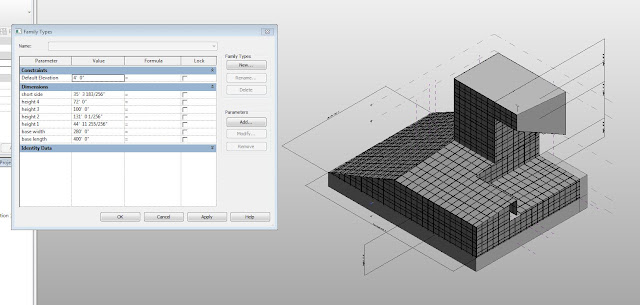
opened with the Edit Family option. In the curtain panels’ family files the
parameter “Material” was added and applied to the portion of the panels that
are the gray and white colored segments. The panels were reloaded into the
project mass, where the Material parameter of the two panel systems could be
manually changed, and the project mass was then reloaded into the Project 1
project file.
Error window when trying to run the .dll command file in Revit project
Select
project mass in project file
Select
curtain panel families in project mass file

Editing
curtain panel families
Addition and application of parameter “Material" to gray and white portions of
curtain panel
“Material” parameter is editable in project file
Result:
still has error when running
I thought that this would resolve the problem, but when the .dll file
was ran again the same error window appeared. After checking and
double-checking the different files that make up Project 1 and trying a few
other things, I currently have not resolved the issue.
Add-In window with .dll file available
Same error appears


